
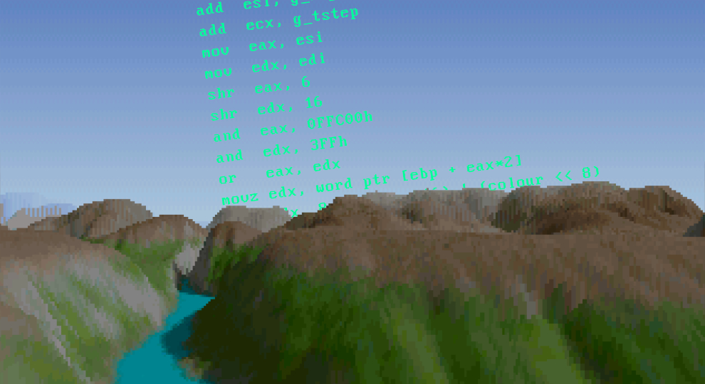
I have always been fascinated by 3D terrain rendering and the way computer graphics can recreate landscapes. Sometimes I think that fascination comes from growing up in the pampas of southern Brazil, where nature stretched out as far as the eye could see. Hills, vegetation, open horizons, and different green shades of woodland and Araucaria trees.
At other times, I wonder if the thrill of rendering my first OpenGL landscape was just me fulfilling a different kind of dream: the dream of seeing those landscapes untouched, without the scars left by human hands and the relentless advance of progress. Through computer graphics, I could imagine a different world... a world that looked like the one I remembered, rather than the one I was forced to watch slowly crumble around me.
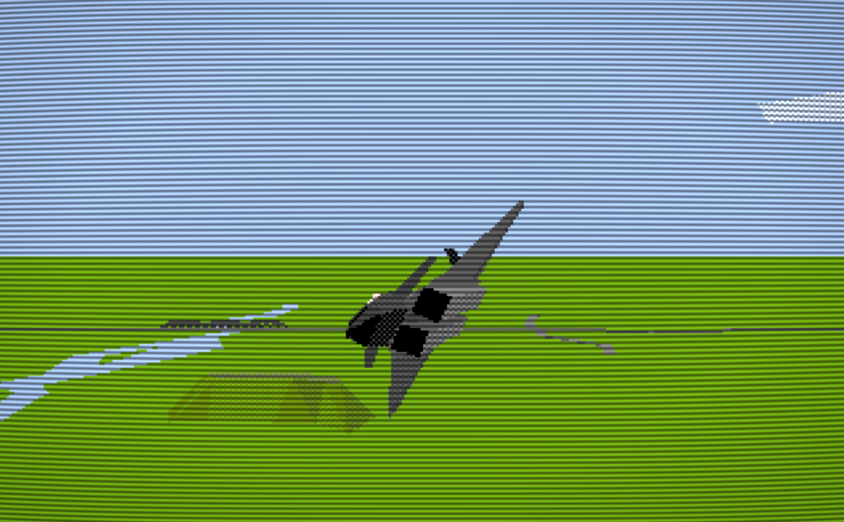
That being said, drawing fancy 3D terrain using OpenGL was not how I started. In the early 90s, we did not have hardware acceleration and high-resolution displays. Back then, every pixel was manually painted via software (CPU). It was the golden era of MS-DOS games, VGA & SVGA graphics, low-poly, flat-shaded, and dithered 3D worlds.
The majority of the flight simulators of the time rendered terrain using polygons. Every 3D object contains vertices, and those vertices are used to compose a polygonal scene that gets projected and rasterized, scanline by scanline, pixel by pixel.
In a decade where most 3D games used polygonal graphics, NovaLogic's Comanche: Maximum Overkill showed rolling mountains, deep canyons, and shaded valleys that looked almost photographic, and it did that on the home's 386 machine.
The technique behind it was called Voxel Space, and it was created by Kyle Freeman. This is probably one of my favorite algorithms of all time, and I've covered how the technique works in one of our previous videos:
If you've followed our Voxel Space tutorial, you know that we use a set of 1024×1024 images: one color map and one height map for each level.
But have you ever asked yourself where those images came from? The game never shipped any GIF files. To generate those GIF files, we need to dig them out of the original game data.
That's exactly what we'll do in this article! We'll open the files that shipped with the 1992 game, look at the raw bytes, work out the format, and then write a small ANSI C program that turns them into BMP images you can open in any image viewer. As you'll see, the answer is a lot less exotic than you might expect, and that's a lesson in itself.
Eyes on the Prize!
Before we open a hex editor, it helps to know what the final result should look like. A Voxel Space terrain needs only two pieces of data:
- A height map: a grid where each byte is the terrain altitude at that point.
- A color map: a grid of the same size where each byte is the color of the ground at that point, with the lighting and shadows already baked in.
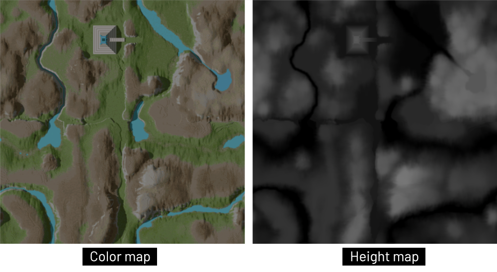
Both grids are 1024×1024. That's exactly 1,048,576 bytes per map, or 1 MB. The color map uses 8-bit indexed color, so each byte is not an RGB value but an index into a 256-color palette. That's perfect for VGA mode 13h, which is also 256 colors.
Keep the number 1,048,576 in mind. If we find something that decompresses to exactly that size, we're on the right track.
Poking Around the Game Folder
The original game folder is a typical early-90s mess of 8.3 file names (8 characters for the name plus 3 characters for the file extension). In our case, we can see multiple .RLE files (probably sprites and sounds), .MIS files (likely for mission data), and a bunch of .DTA files. Among them, eight files immediately stand out because of their size:
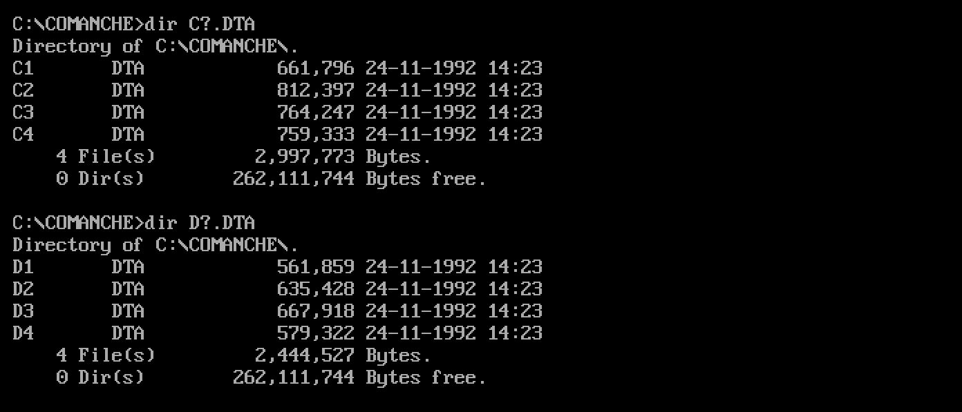
It looks like these files come in pairs, numbered 1 to 4 and using the prefix C and D.
My first guess is that C stands for "color" and D for "depth" (the height map). They're all smaller than 1 MB, so whatever is inside must be compressed.
When I'm reverse engineering a file format, the first thing I do is to use a hex editor to explore the first few bytes of the file. Here are the first bytes of C1.DTA:
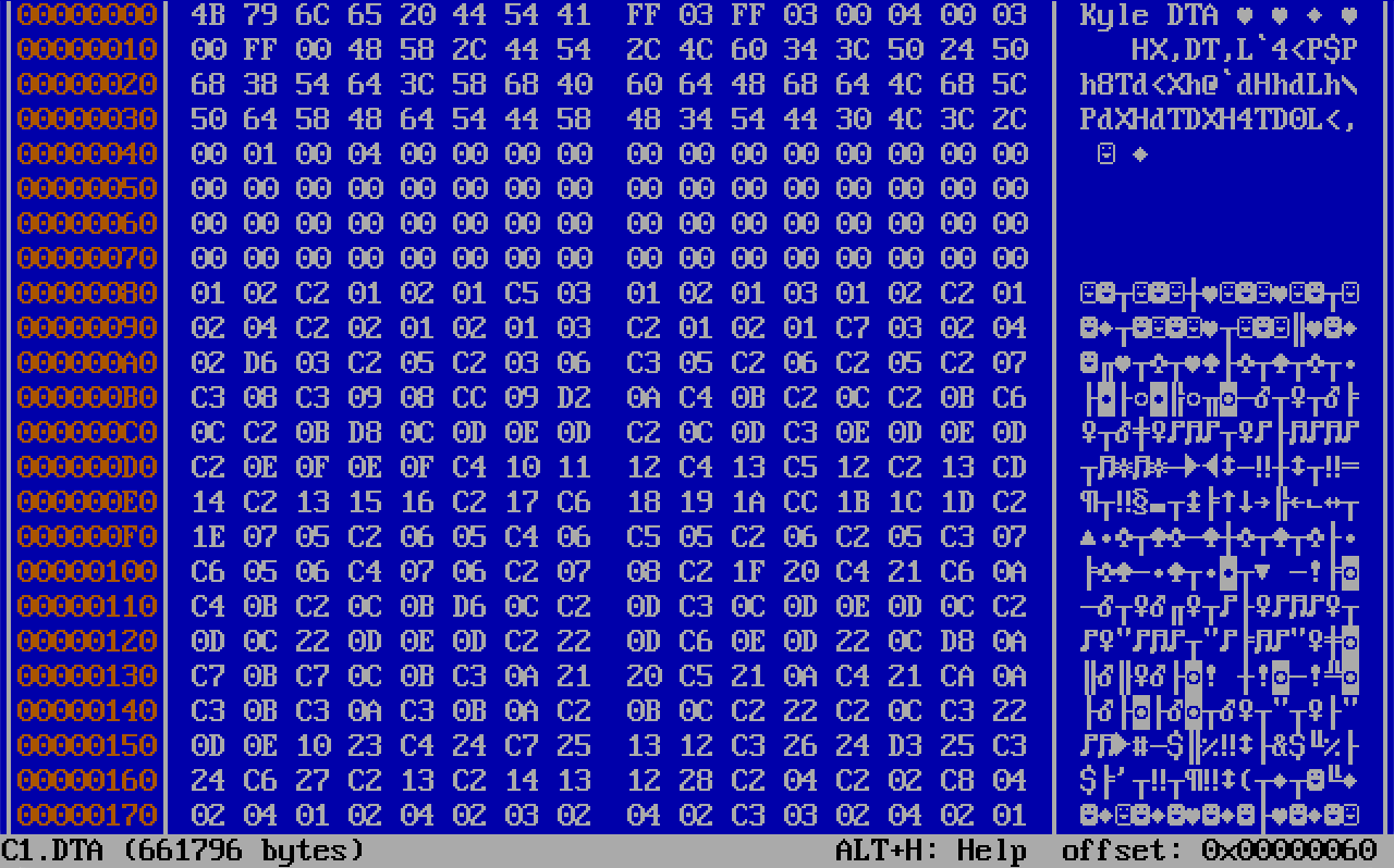
The first eight bytes spell out Kyle DTA. That's a signature from Kyle Freeman himself, sitting at the top of every map file. It also looks like all four C files and all four D files start the same way.
The rest of the dump gives us three more clues:
- At offset
0x08we seeff 03 ff 03. Read as 16-bit little-endian numbers, that's 1023 and 1023, which is suspiciously close to 1024×1024. - At offset
0x42we see00 04, which is 1024. - The header seems to end at offset
0x80(128). After a block of zeros, the data changes character completely.
Here's what comes right after the header in our file:
00000080: 01 02 c2 01 02 01 c5 03 01 02 01 03 01 02 c2 01  ................
00000090: 02 04 c2 02 01 02 01 03 c2 01 02 01 c7 03 02 04  ................
Notice how many bytes are C2, C5, or C7, and how each one is followed by what looks like an ordinary small value. Well, if you've spent any time with DOS-era image formats, this should ring a bell.
A PCX in Disguise
A 128-byte header, image dimensions stored as maximum coordinates (1023 instead of 1024), and a stream of bytes where the top two bits are often set. Those are all fingerprints of PCX, the ZSoft Paintbrush format that was everywhere on DOS in the late 80s and early 90s.
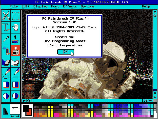
A normal PCX file starts with the byte 0x0A (the ZSoft "manufacturer" ID), followed by a version number, an encoding flag, and the bits per pixel. Then come four 16-bit coordinates: xmin, ymin, xmax, and ymax. Together, these first fields take exactly 8 bytes.
And it looks like that's exactly what NovaLogic did! They took a standard 8-bit PCX file and overwrote its first 8 bytes with the text Kyle DTA. Every other field is still in its usual place:
| Offset | Size | PCX field | Value in C1.DTA |
|---|---|---|---|
0x00 | 8 | manufacturer, version, encoding, bits per pixel, xmin, ymin | replaced with Kyle DTA |
0x08 | 2 | xmax | 1023 |
0x0A | 2 | ymax | 1023 |
0x0C | 4 | horizontal and vertical DPI | 1024, 768 (ignored) |
0x10 | 48 | 16-color EGA palette | unused |
0x40 | 1 | reserved | 0 |
0x41 | 1 | number of color planes | 1 |
0x42 | 2 | bytes per scan line | 1024 |
0x44 | 60 | palette info and padding | zeros |
0x80 | ... | compressed pixel data | RLE stream |
The width is xmax + 1 and the height is ymax + 1, so 1024×1024. One plane at one byte per pixel means one 8-bit index per pixel, which is exactly what we were looking for.
Why hide a PCX file like this? We can only guess. Maybe it was to stop us from opening the maps in Deluxe Paint. Maybe it was simply a way for the loader to check that it had been handed the right kind of file.
The disguise is only skin deep, though. If you put back the 8 bytes of a standard PCX header (0a 05 01 08 00 00 00 00) and rename the file to .PCX, any image viewer that understands PCX will be able to open the map.
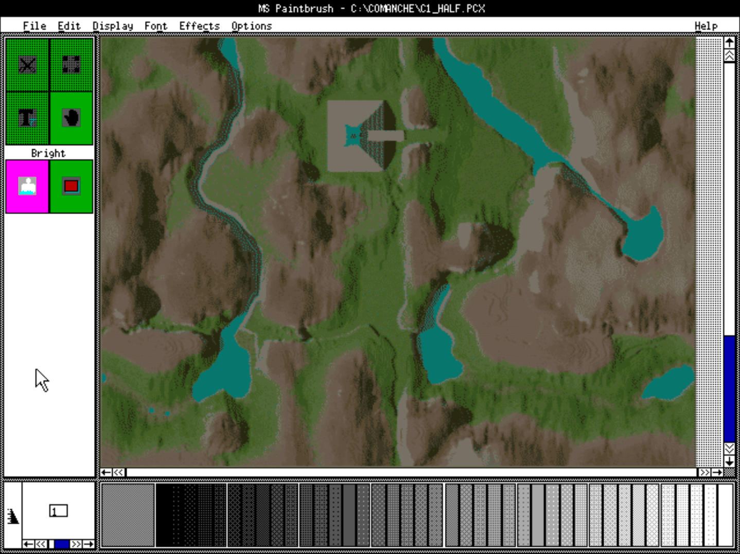
Fun fact: the DPI field isn't consistent across the files. C2.DTA says 800×600, and C3.DTA and C4.DTA say 1024×1024. Those values most likely just record the settings of whatever tool the artists saved them with.
Decoding the RLE Stream
The PCX file format uses one of the simplest compression schemes there is: run-length encoding (RLE).
If you ever took our NES Assembly Programming course, you probably remember decoding level data from the cartridge using RLE. The idea is pretty simple... instead of storing 05 05 05 05 05 05 05, you store 07 05 ("seven copies of 05"). We might expect terrain textures to have lots of neighboring pixels with the same value, so this can hopefully save a good amount of space. It's also very cheap to decode, which mattered on a 386 PC.
The rule for PCX is:
- If the two top bits of a byte are set (
b >= 0xC0), the byte is a counter. Its lower six bits say how many times to repeat the byte that follows. - Otherwise, the byte is a literal pixel value and is copied as it is.
Let's decode the start of the data we saw before, 01 02 c2 01 02 01 c5 03:
01      -> 01
02      -> 02
c2 01   -> 01 01            (0xC2 & 0x3F = 2 copies)
02      -> 02
01      -> 01
c5 03   -> 03 03 03 03 03   (0xC5 & 0x3F = 5 copies)
There's one catch worth mentioning! What if a single pixel has a value of 0xC0 or higher? The decoder would mistake it for a counter. The encoder avoids that by always writing those values as a run of one: C1 D7 means one pixel of value 0xD7. Since a run can be at most 63 pixels long, you'll also see long stretches of the same color split into several runs.
In C, the whole decoder fits in a single loop. data holds the entire file, and we start reading right after the 128-byte header:
/*****************************************
* PCX run-length decoding routine
* Starts right after the 128-byte header
******************************************/
pos = 128;
n = 0;
while (n < total && pos < size) {
  unsigned char b = data[pos++];
  if ((b & 0xC0) == 0xC0) {
    int count = b & 0x3F;
    unsigned char value = data[pos++];
    while (count-- && n < total) {
      img->pixels[n++] = value;
    }
  } else {
    img->pixels[n++] = b;
  }
}
In the Comanche maps a run never continues from one row into the next, so we can decode the whole image as one long stream. After exactly 1,048,576 pixels, the loop stops, and that's the number we were hoping to see.
The Palette Hiding at the End
We have a million bytes of color indices, but indices into what? The 48-byte palette in the header only has room for 16 colors, and the Comanche maps don't use it.
PCX version 5 added support for 256-color images by putting the palette at the very end of the file. The format is simple: a single marker byte 0x0C, followed by 256 RGB triplets (768 bytes). Our decoder stopped at exactly 1,048,576 pixels, and if you check how many bytes are left in the file at that point, the answer is 769 for every one of the eight maps. That's the marker plus the palette.
/***********************************
* 256-color palette: Marker 0x0C.
* Followed by 768 bytes at the end
************************************/
if (size >= 769 && data[size - 769] == 0x0C) {
  memcpy(img->palette, data + size - 768, 768);
}
One detail worth knowing if you plan to use these colors on real VGA hardware: PCX stores each component with 8 bits (0 to 255), but the VGA DAC only takes 6 bits per component (0 to 63). When you send this palette to ports 0x3C8/0x3C9 in mode 13h, shift each value right by 2 first.
One detail that was fun to find was that height map files also have a palette! It is not simply a gray ramp. It's a false-color palette split into bands of 16 shades each: blues, then oranges, and so on, with a gray band further up and magenta filling the unused entries. Open a D file in a paint program with this palette and you get a contour map, where each color band covers 16 height units. I'll try to confirm this with Kyle Freeman himself, but I can definitely see NovaLogic artists using exactly that view to paint and check their terrain files.
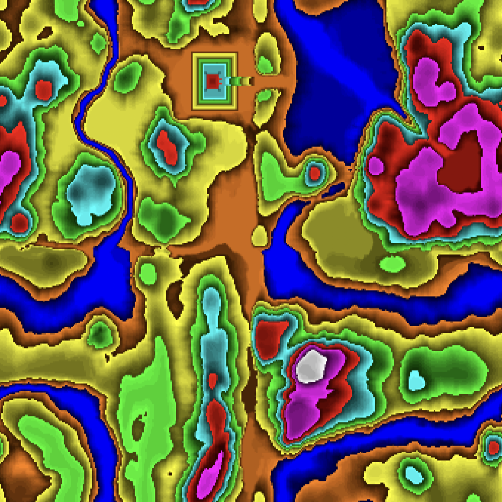
For our purposes we'll ignore the height palette and use a plain gray ramp instead, so that the pixel value is the height: black is the lowest point, and brighter means higher. The heights in the four maps only go from 0 to about 120, so the images will look quite dark. That's expected: the values are raw altitudes, not a picture meant to be looked at.
Writing an 8-bit BMP
Well, after we understand the PCX format, creating a BMP version of the files should be easy enough.
Now that we have pixels and a palette in memory, we need to save them in a format that modern tools understand. I'll use BMP, because an uncompressed 8-bit BMP is about the easiest image format you can write by hand: two small headers, a palette, and the raw pixels.
The structure looks like this:
| Part | Size | Contents |
|---|---|---|
BITMAP FILEHEADER | 14 bytes | BM signature, file size, offset to the pixel data |
BITMAP INFOHEADER | 40 bytes | width, height, 1 plane, 8 bits per pixel, no compression |
| Color table | 256 × 4 bytes | each color as blue, green, red, 0 |
| Pixel data | height × row size | one byte per pixel, rows padded to a multiple of 4 bytes |
There are three traps that catch everyone the first time:
- BMP stores colors as BGR, not RGB, and each color takes 4 bytes instead of 3.
- With a positive height, the rows are stored bottom-up: the last row of the image comes first in the file.
- Every field is little-endian. We'll write the bytes one at a time, so the code works the same on any CPU, whatever its byte order.
First, two helpers to write 16-bit and 32-bit values in little-endian order:
static void write_u16(FILE *f, unsigned int v) {
  fputc(v & 0xFF, f);
  fputc((v >> 8) & 0xFF, f);
}

static void write_u32(FILE *f, unsigned long v) {
  write_u16(f, (unsigned int)(v & 0xFFFF));
  write_u16(f, (unsigned int)(v >> 16));
}
And here's the function that writes the whole file:
static int save_bmp(const char *filename, const image_t *img) {
  FILE *f;
  int i, y;
  unsigned long row_size = (img->width + 3) & ~3UL;    /* rows padded to 4 bytes */
  unsigned long pixel_offset = 14 + 40 + 256 * 4;
  unsigned long file_size = pixel_offset + row_size * img->height;

  f = fopen(filename, "wb");
  if (!f) {
    return 0;
  }

  /* BITMAPFILEHEADER (14 bytes) */
  fputc('B', f); fputc('M', f);
  write_u32(f, file_size);
  write_u32(f, 0);                 /* reserved */
  write_u32(f, pixel_offset);

  /* BITMAPINFOHEADER (40 bytes) */
  write_u32(f, 40);
  write_u32(f, img->width);
  write_u32(f, img->height);    /* positive = rows stored bottom-up */
  write_u16(f, 1);                 /* planes */
  write_u16(f, 8);                 /* bits per pixel */
  write_u32(f, 0);                 /* no compression */
  write_u32(f, row_size * img->height);
  write_u32(f, 2835);              /* 72 DPI */
  write_u32(f, 2835);
  write_u32(f, 256);               /* colors used */
  write_u32(f, 0);

  /* palette: BMP wants blue, green, red, reserved */
  for (i = 0; i < 256; i++) {
    fputc(img->palette[i * 3 + 2], f);
    fputc(img->palette[i * 3 + 1], f);
    fputc(img->palette[i * 3 + 0], f);
    fputc(0, f);
  }

  /* pixel rows, last row first */
  for (y = img->height - 1; y >= 0; y--) {
    unsigned long pad;
    fwrite(img->pixels + (long)y * img->width, 1, img->width, f);
    for (pad = img->width; pad < row_size; pad++) {
      fputc(0, f);
    }
  }
  fclose(f);
  return 1;
}
Our maps are 1024 pixels wide, which is already a multiple of 4, so the padding loop never runs. I kept it anyway so the function works for any width.
What About GIF?
The images we used in our original voxel space tutorial/code were GIFs. So, why not write a GIF directly? Because GIF compresses its pixels with the LZW method, and a correct LZW encoder with variable code sizes would be a whole article of its own.
A Bit of History: For most of the 90s, LZW was covered by a Unisys patent, and when Unisys announced royalties for it at the end of 1994, the reaction was big enough to give birth to the PNG format.
The good news is that we don't need it. Our BMP is 8-bit indexed with a 256-color palette, exactly like a GIF, so converting it loses nothing. Any tool like ImageMagick would do.
Putting It All Together
Let's glue everything into one small command-line tool. We'll store each decoded image in a simple struct:
typedef struct {
  int width, height;
  unsigned char *pixels;       /* width * height palette indices */
  unsigned char palette[768];  /* 256 RGB triplets, 8 bits each  */
} image_t;
The loader reads the whole file into memory, checks the Kyle DTA signature, reads the dimensions from the header, and then runs the RLE loop and the palette copy we saw earlier:
static unsigned int read_u16(const unsigned char *p) {
  return p[0] | (p[1] << 8);
}

static int load_dta(const char *filename, image_t *img) {
  FILE *f;
  long size, pos, n, total;
  unsigned char *data;

  f = fopen(filename, "rb");
  if (!f) {
    return 0;
  }
  fseek(f, 0, SEEK_END);
  size = ftell(f);
  fseek(f, 0, SEEK_SET);
  data = (unsigned char *)malloc(size);
  if (fread(data, 1, size, f) != (size_t)size || memcmp(data, "Kyle DTA", 8) != 0) {
    fclose(f);
    free(data);
    return 0;
  }
  fclose(f);
  img->width  = read_u16(data + 8)  + 1;   /* xmax + 1 */
  img->height = read_u16(data + 10) + 1;   /* ymax + 1 */
  total = (long)img->width * img->height;
  img->pixels = (unsigned char *)malloc(total);

  /* ... RLE decoding loop ... */
  /* ... palette copy ... */

  free(data);
  return 1;
}
Finally, main() takes a map number, converts both files of the pair, and swaps the height map's palette for a gray ramp:
int main(int argc, char *argv[]) {
  char in_name[256], out_name[256];
  image_t color, height;
  int map, i;

  if (argc < 2) {
    printf("usage: dta2bmp <map number 1-4>\n");
    return 1;
  }
  map = atoi(argv[1]);

  sprintf(in_name, "C%d.DTA", map);
  if (!load_dta(in_name, &color)) {
    printf("Could not read %s\n", in_name);
    return 1;
  }
  sprintf(out_name, "map%d_color.bmp", map);
  save_bmp(out_name, &color);

  sprintf(in_name, "D%d.DTA", map);
  if (!load_dta(in_name, &height)) {
    printf("Could not read %s\n", in_name);
    return 1;
  }
  for (i = 0; i < 256; i++) {      /* gray ramp: index = height */
    height.palette[i * 3 + 0] = (unsigned char)i;
    height.palette[i * 3 + 1] = (unsigned char)i;
    height.palette[i * 3 + 2] = (unsigned char)i;
  }
  sprintf(out_name, "map%d_height.bmp", map);
  save_bmp(out_name, &height);

  printf("map %d: %dx%d color + height maps saved\n", map, color.width, color.height);
  free(color.pixels);
  free(height.pixels);
  return 0;
}
The whole program is about 150 lines of plain ANSI C.
And here's the result for the first map, with the color map on the left and the height map on the right:
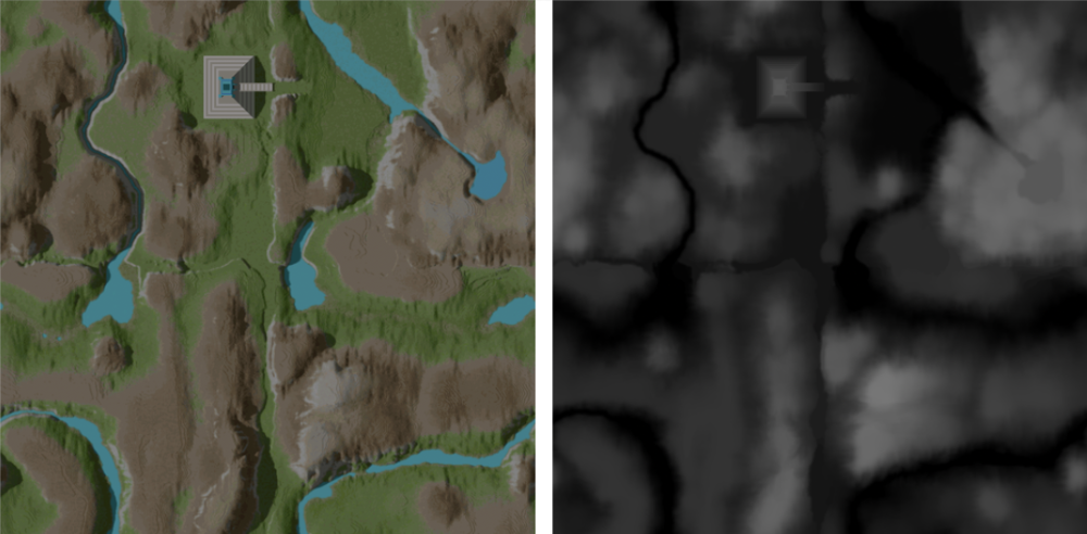
You can see how the two images line up: the rivers are the darkest valleys in the height map, and the brightest areas are the snowy mountain tops. Look at the top-left corner too. That square structure is part of a base painted directly into both maps, with the height raised to match. In Voxel Space, the buildings are part of the terrain.
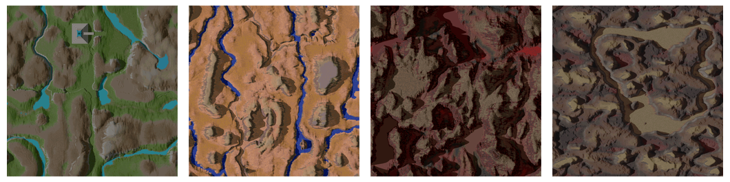
Here are all four color map terrains from the original game:
Checking Our Work
How do we know we got it right? We can compare our output with the maps that have been going around the internet for years, which are numbered from map0. Our map 1 is map0, map 2 is map1, and so on.
- The height map
D1.DTAmatchesmap0byte for byte. The files have the same MD5 hash. - The color map
C4.DTAgives exactly the same RGB colors asmap3on every pixel.
The other maps are almost identical. The differences are in the water: the versions going around online paint every lake and river with palette entries 251 to 254, which are probably used for color-cycling water animation. Some of their heights also differ by one unit. Our files come from the original 1992 release, so the online versions were most likely taken from a later edition of the game. It's a nice reminder that game data changed from release to release, even when the file names stayed the same.
How Were the Map Files Generated?
So how did Kyle Freeman create these maps in the first place? A magazine profile of him from July 1994 tells a little bit of the story. He first tried to build his worlds in a 3D modeling package, but even with detail levels set in the 5 to 6 million polygon range, the results didn't reach the level of realism he wanted. So he did what any good hacker would do: he wrote his own tools. Using programs of his own creation, Freeman sculpted the terrain by hand, "pushing the shapes around and molding the landscape as if it were clay."
Even then, he felt the result looked too soft and too artificial. His solution was to write a few more routines that would morph his voxel worlds by simulating a few million years of erosion, a few seismic disasters, and the constant pummeling of the weather. According to the article, each voxel in his tools stored more than just height and color. It also stored the density of the material at that point, for the rocks, the soil types, and the water. His erosion algorithms took that density into account, so soft soil washed away while hard rock stayed put, carving out the crevasses and valleys we still see in these maps today. None of that extra information made it into the .DTA files we decoded, though. By the time the maps shipped, all that geological work had been baked down into two simple 8-bit images: one byte of color and one byte of height per point.
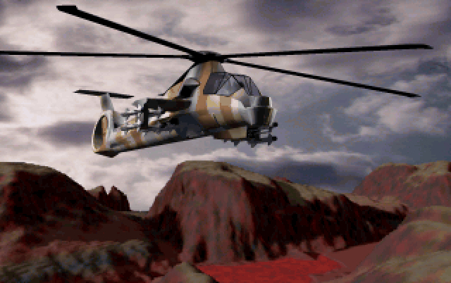
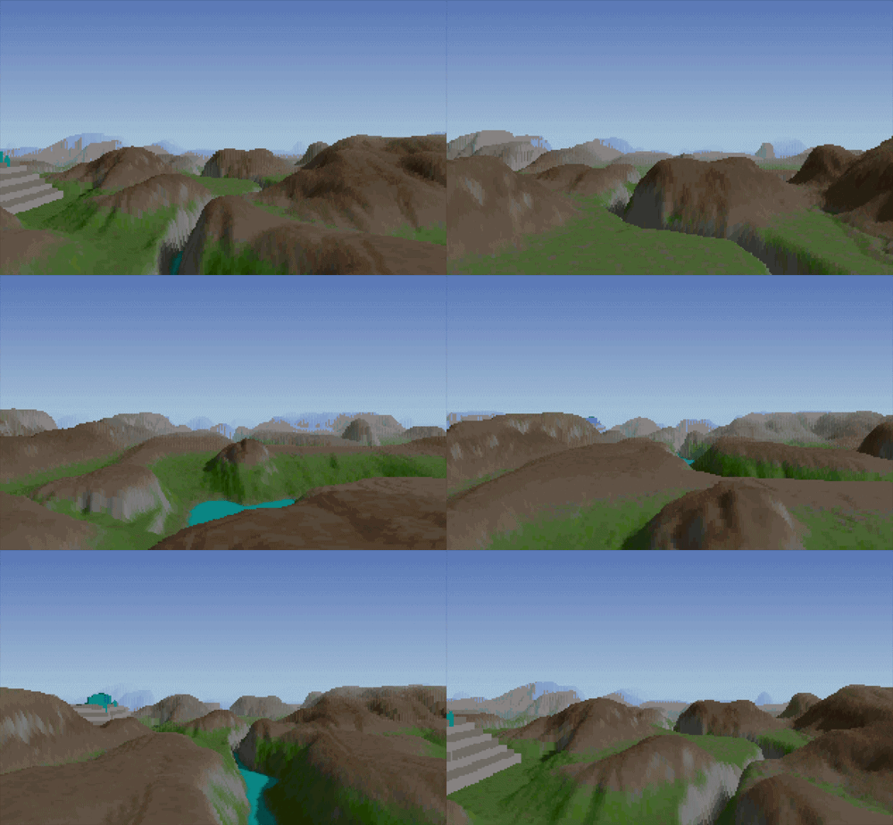
According to Kyle Freeman himself, this terrain tool was probably as complex as the voxel space engine itself. The same techniques used to render the terrain at runtime were also used to generate posters and other marketing material.
Conclusion & Next Steps
When I started looking at these files, I half expected some clever custom compression, the kind of thing you'd expect from a studio that had just invented a new way of drawing terrain. Instead, the maps turned out to be plain PCX images with a signature pasted over the first 8 bytes.
I think that's the real lesson here. Programmers in the early 90s didn't reinvent everything. They used the formats and tools the artists already had, like PCX files straight out of a paint program, and saved their cleverness for the parts that really needed it: the renderer. And when you reverse engineer an old file format, the approach is almost always the same. Look at the first bytes, find anything that looks like a size or a count, and ask yourself which common format of the era it resembles.
Now that we have the maps as plain images, the fun part begins. Load them into your own Voxel Space renderer, or go all the way back to DOS and draw them in VGA mode 13h with the original 256-color palette, just like in 1992.
And that's it for our quick look inside the Comanche map files. If you have any suggestions for this article, you can yell at me on Twitter. Also, remember to visit the courses page to access my lectures on retro programming.
See you next time!