
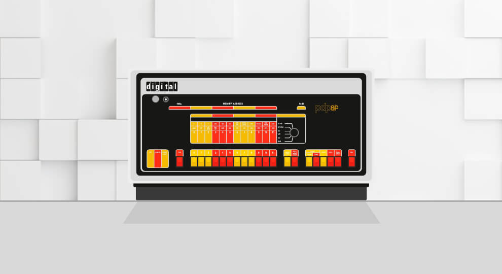
There is something deeply satisfying about looking at an old machine and realizing that, underneath all the blinking lights, switches, registers, and instructions, it is still possible to fully grasp the fundamental building blocks of a traditional computer.
If you're not new here, you probably know that, in our school, we often look back in time to understand how technology evolved. Studying the early days of computing allows us to take advantage of a type of simplicity that can only be found in older and more rudimentary systems. Even though modern technology is extremely complex, computers are, ultimately, just a very large collection of tiny circuits that manipulate bits. Retro architectures are a great way to fully grok the basic concepts of digital circuits and computers.
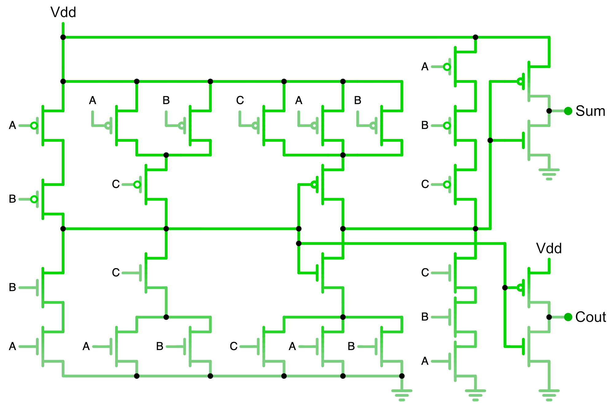
Computers are huge abstraction machines. You can start by understanding how electricity works and how it behaves, then we proceed to understand how transistors can behave like switches, then how a handful of transistors can form logic gates, then how logic gates can form adders, multiplexers, latches, and registers. We connect these circuits together to form an arithmetic & logic unit, then we add a control unit, some memory, and a clock, and suddenly we have a simple but working CPU.
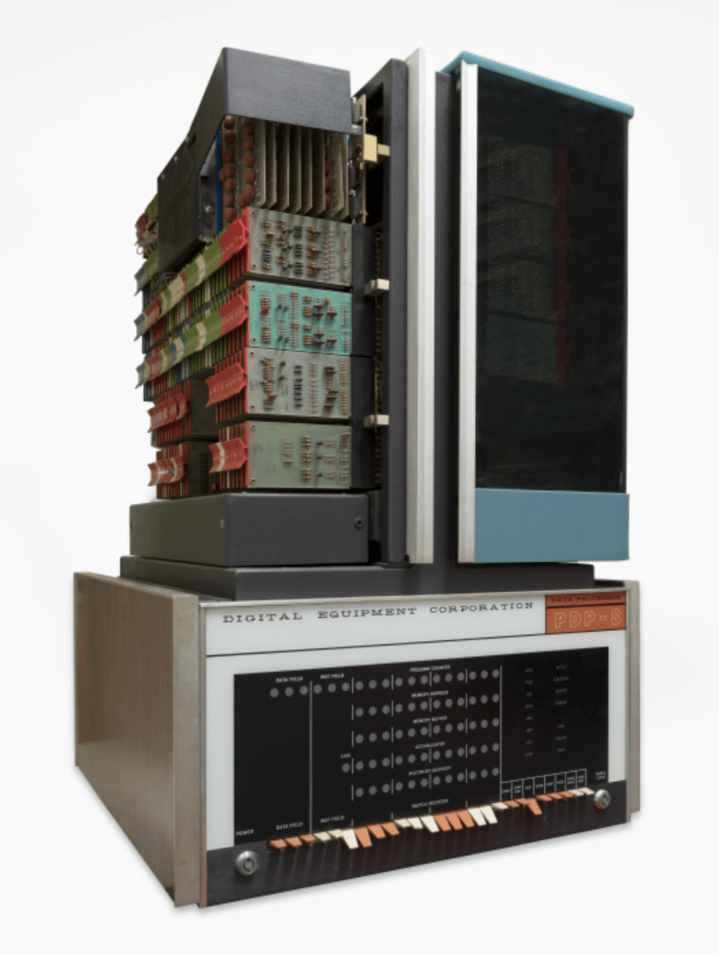
A great example of computer that is simple enough for us to dissect how basic digital circuits work is the DEC PDP-8. Introduced in 1965, the PDP-8 is a classic, textbook example of an accumulator-based architecture, and it was one of the most influential early minicomputers. More importantly for us, its architecture is small enough that we can understand a surprisingly large part of the machine without getting buried in complexity.
The PDP-8 is a 12-bit computer that has a tiny instruction set, a single main accumulator, a peculiar memory-addressing scheme, a one-bit link register, instructions that perform several jobs at once, and even a handful of registers that aren't actually registers at all.
And perhaps the strangest thing about it is that these aren't arbitrary historical oddities. They are the consequences of trying to build a useful computer out of expensive hardware.
A Computer Small Enough to Sell
To understand the PDP-8, we need to go back to the early 1960s.
Computers were expensive machines. A typical computer belonged in a computer center, not on someone's desk. The idea of buying a general-purpose computer for a laboratory, factory, or engineering department was still unusual.
Digital Equipment Corporation, founded in 1957 by Ken Olsen & Harlan Anderson, was already building smaller computers. Its PDP-5, introduced in 1963, was an important predecessor to the PDP-8.

The PDP-8 arrived in March 1965 and pushed the idea much further. It was a 12-bit general-purpose computer that could be purchased for around $18,000, which was dramatically less than the machines that dominated computing at the time.
The first PDP-8 used discrete transistor logic rather than a microprocessor. Its CPU was constructed from small plug-in circuit modules known as Flip-Chips, connected through wire-wrapped backplanes.
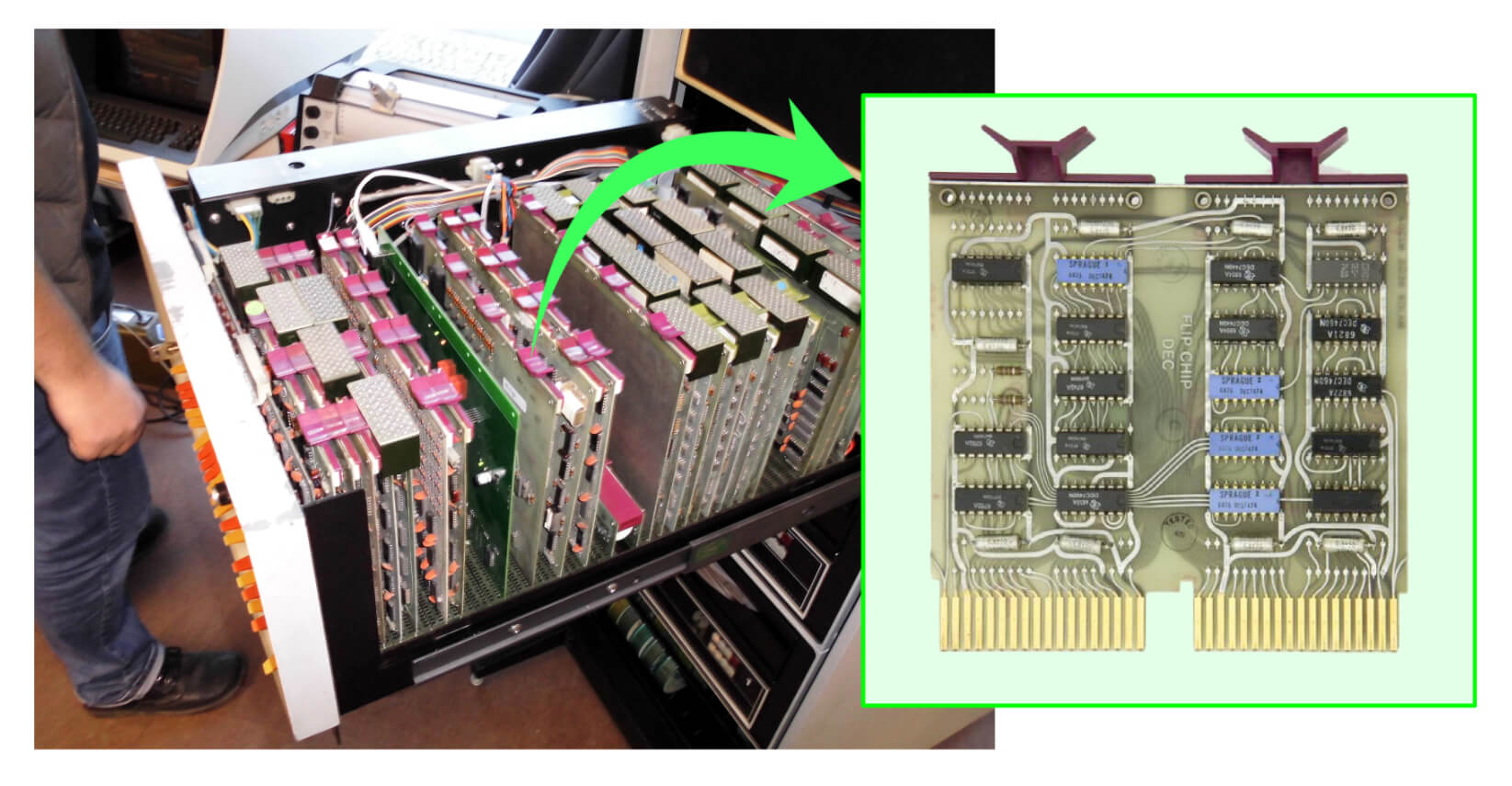
It was therefore a computer in the most literal sense. You could open the machine and see the circuitry that implemented the processor. There was no CPU chip hiding underneath a heat spreader. The central processing unit was the collection of circuit boards.
Why 12 Bits?
Today, 8, 16, 32, and 64-bit computers feel natural, while 12 bits might feel strange. But 12 is actually a very convenient number for the PDP-8.
A 12-bit word gives us 4096 (2¹²) possible values. More importantly, 12 divides nicely into three groups of four bits. That makes the machine's binary representation fairly compact and convenient for its designers and programmers.
The PDP-8's original memory contained 4K words of 12-bit core memory, which gives us a machine where an entire word is small enough to understand, but large enough to hold a useful instruction, a character-oriented value, or a small integer.
The 12-bit architecture was retained throughout the PDP-8 family even as the implementation technology changed dramatically.
A Family of PDP-8s
Before we continue, it's important to point out that, when we talk about the PDP-8, we're actually talking about a whole family of machines. I want to get this out of the way now, because you'll see many images online (including the ones in this article) and they might be from different models of PDP-8.
DEC kept the basic 12-bit architecture remarkably consistent, but the electronics underneath changed quite dramatically over the years. Some models were cheaper, some were faster, and some were essentially experiments in how to build the same computer with less hardware.
The Original PDP-8
The original PDP-8, introduced in 1965, was built from discrete transistor logic and magnetic-core memory. It was a relatively compact machine for its time, but its CPU was still made from a large collection of individual circuit modules. This is the machine that established the PDP-8 architecture and helped make the minicomputer commercially successful.
The PDP-8/S
The PDP-8/S, introduced in 1966, took a particularly interesting approach Instead of building a wide, parallel arithmetic unit, the 8/S performed many operations serially, one bit at a time. This saved circuitry and therefore reduced the cost, but it also made the machine considerably slower. It's a great example of an architectural idea surviving while the underlying hardware is radically rearranged.
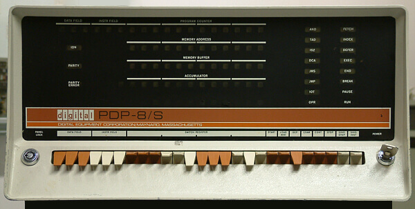
The PDP-8/I
The PDP-8/I moved the design toward integrated circuits (ICs), making the computer smaller, cheaper, and more practical. Rather than constructing the processor from the earlier discrete-transistor modules, DEC could now use integrated logic to pack much more functionality into a smaller space.
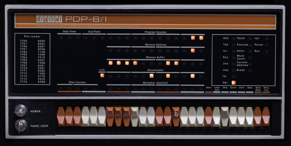
The PDP-8/E
The PDP-8/E, from 1970. was one of the most important models because it became the basis for a large ecosystem of PDP-8 systems and peripherals. It used newer IC technology, had a modular backplane, and could be expanded with a wide variety of memory and I/O options. The large machine in the photograph below is an example of the kind of system that could be built around the 8/E architecture.
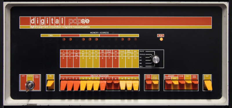
The PDP-8/F
The 8/F was essentially a lower-cost version of the 8/E. It retained the PDP-8 architecture but simplified the physical implementation and packaging. DEC was becoming very good at taking the same architectural idea and finding cheaper ways to manufacture it.
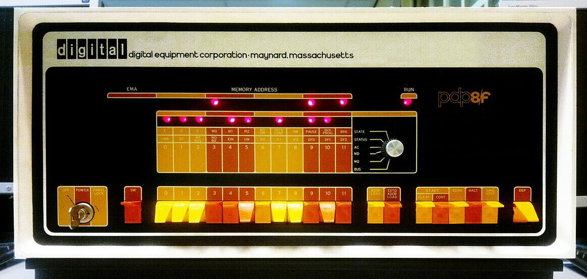
The PDP-8/A
There was also thePDP-8/A, which pushed the idea of a small, inexpensive PDP-8 even further. It was designed around newer technology and was particularly attractive for OEMs and embedded-control applications. By this point, a PDP-8 didn't necessarily look like the large minicomputer we might imagine from photographs of early systems—it could be a relatively compact computer hidden inside another machine.
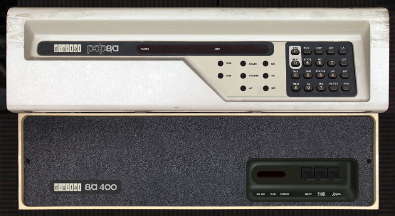
One important thing to notice is that these machines were not simply a sequence of increasingly powerful CPUs. In many cases, DEC was keeping the programming model stable while changing the implementation underneath it. A program written for the PDP-8 architecture could therefore survive several generations of hardware. The electronics could change from discrete transistors to integrated circuits, the memory could change, the packaging could change, and the machine could become dramatically cheaper, while the programmer could still think in terms of the same 12-bit accumulator, program counter, LINK bit, memory-reference instructions, and I/O instructions.
This stability was one of the reasons that the PDP-8 family is so interesting from an architectural perspective. The different models are almost like experiments in implementation: "How cheaply, quickly, or compactly can we build essentially the same computer?"
PDP-8/E Field Guide
This is a fully-configured PDP-8/E, DEC's mid-1970s 12-bit minicomputer. This was arguably the machine that made "minicomputer" an affordable word. What looks like one cabinet is three bays bolted together: processor and paper-tape I/O on the right, DECtape storage in the middle, and disk storage on the left. Tap any numbered lamp for details.

Model nameplate
Digital Equipment Corp's builder's plate, identifying this exact machine as a PDP-8/E. The matching orange-to-gold stripe repeats across the top of all three bays, color-coding them as one system rather than three separate cabinets.
CPU & operator's console
The processor itself lives behind this panel, on the Omnibus backplane (along with its core memory). The amber lamps display the live contents of the memory-address register, so you're watching the CPU's program counter tick in real time. The toggle switches below are the switch register, used to key in a bootstrap address or deposit/examine memory by hand.
Paper-tape reader/punch
A high-speed paper-tape I/O unit (popularly called "the PUNCH") control is visible at lower right. Before disks were standard equipment, punched paper tape was the everyday way programs and data moved in and out of a PDP-8.
Spare reel storage
An empty, spring-loaded reel rack sized for the same small reels used by the DECtape drives at center (currently unloaded).
DECtape control & status panel
Diagnostic lamps for the DECtape controller's internal logic (not user data). Visible legends include WC (word count) and STATE, tracking the controller's read/write sequencing as it services the drives below.
DECtape reel storage
Reels for DECtape proper. This was a lower-capacity but block-addressable format, popularly called the "tape you could compute on." Unlike ordinary magnetic tape, it supported random access and safe read-while-writing.
TU56 DECtape transports
Two dual-transport decks stacked here (four tape units in total). Each transport has its own WRITE ENABLE and REMOTE/LOCAL switches. DECtape was DEC's affordable answer to semi-random-access storage in the years before disk drives were cheap enough for every system.
RK05J disk-cartridge drives
Two disk drives, each labeled decpack RK05J. Every drive takes one removable, top-loading disk cartridge (racked just above). This was roughly 1.6MB per pack, which was a serious leap over tape for running an OS and holding files.
Disk-cartridge storage
Spare RK05 cartridges racked directly above their drives, hand-labeled by whoever ran this system.
Blank filler panels
The large plain panels repeated through all three bays aren't dead space. They're covers over the card cage, wiring, and power supplies doing the real work behind each visible control panel.
Let's take a look inside the PDP-8's CPU to better understand its electronics and its computer architecture.
The PDP-8 CPU is Tiny
If you look at a modern CPU architecture diagram, you'll find a bewildering collection of registers.
PDP-8 is almost comically different. The programmer-visible core of the machine includes a 12-bit program counter, a 12-bit accumulator, and a single link bit. There were additional registers in the hardware, but many things that we'd expect to be registers are instead implemented using memory.
Well, relatively cheap. In 1965, adding another register wasn't something you casually did. A register meant more circuitry.
So, instead of giving the programmer eight general-purpose registers, the PDP-8 gives you one accumulator and asks you to use memory for everything else.
It was inconvenient, but it was also incredibly economical.
Essential PDP-8 Instructions
The PDP-8 has a wonderfully small instruction set. Every instruction is exactly 12 bits wide, with the first three bits broadly identifying the instruction group.
Only Eight Basic Opcodes
Here's another PDP-8 curiosity. The "instruction word" is only 12 bits wide, and the first three bits determine one of eight primary instruction groups:
000: AND   // Logical AND
001: TAD   // Twos-Complement ADD
010: ISZ   // Increment and Skip if Zero
011: DCA   // Deposit and Clear Accumulator
100: JMS   // Jump to Subroutine
101: JMP   // Jump
110: IOT   // I/O Transfer
111: OPR   // Operate on Bits
That's it. Only eight!
At first, this looks absurdly small. But for the PDP-8, several of these aren't really single instructions; they are instruction families.
The table below contains some of the most important instructions needed to understand the examples and architectural ideas discussed in this article. Note how the first three bits of the instruction are really the main group to which it belongs.
| Op | Meaning | 12-bit | What it does |
|---|---|---|---|
AND |
Logical AND | 000 I Z AAAAAAA |
AC ← AC AND M[address] |
TAD |
Two's complement Add | 001 I Z AAAAAAA |
AC ← AC + M[address], with overflow/carry affecting LINK |
ISZ |
Increment and Skip if Zero | 010 I Z AAAAAAA |
Increment a memory word; skip the next instruction if the result is zero |
DCA |
Deposit and Clear Accumulator | 011 I Z AAAAAAA |
M[address] ← AC, then AC ← 0 |
JMS |
Jump to Subroutine | 100 I Z AAAAAAA |
Store the return address in memory and jump to the subroutine |
JMP |
Jump | 101 I Z AAAAAAA |
PC ← address |
IOT |
Input/Output Transfer | 110 DDDDDD OOO |
Communicate with an I/O device; the device and operation are encoded in the instruction |
OPR |
Operate | 111 xxxxxxxxx |
A family of instructions where individual bits select operations on AC and LINK |
CLA |
Clear Accumulator | 111 1 00000000 |
AC ← 0 |
CLL |
Clear Link | 111 0 10000000 |
LINK ← 0 |
CMA |
Complement Accumulator | 111 0 01000000 |
Invert every bit in AC |
IAC |
Increment Accumulator | 111 0 00000001 |
AC ← AC + 1 |
RAR |
Rotate Right | 111 0 00001000 |
Rotate the combined 13-bit LINK:AC value one position right |
RAL |
Rotate Left | 111 0 00000100 |
Rotate the combined 13-bit LINK:AC value one position left |
HLT |
Halt | 111 1 00000010 |
Stop the processor |
For the six memory-reference instructions (AND, TAD, ISZ, DCA, JMS, and JMP), the format is particularly important:
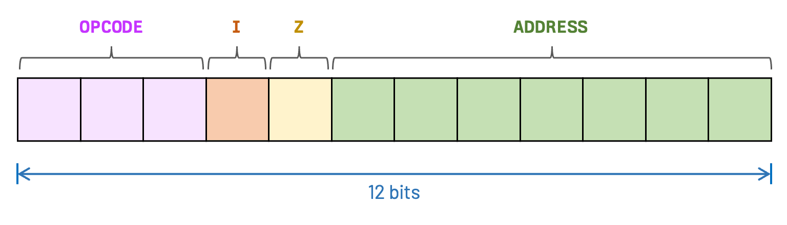
The I bit selects direct or indirect addressing. The Z bit selects either page zero or the current page. The final seven bits select one of the 128 words within that page.
This compact format is one of the reasons the PDP-8 is so interesting: an entire instruction, including its opcode and addressing information, has to fit into just 12 bits.
JMP or TAD. These mnemonics are useful and can be used when an assembler is present, but PDP-8 programmers would often need to enter these instructions using raw machine code via the front panel or via paper-tape.
The Accumulator: The Center of the PDP-8 Universe
The PDP-8 is a classic example of an accumulator machine. Its accumulator, AC, is 12 bits wide. Almost all arithmetic and logical operations revolve around it.
For example, the simple two's-complement addition instruction (TAD) below:
    TAD X

X,   0007
|
Boils down to:
AC ← AC + Memory[X]The accumulator will store the result of the addition operation performed between the accumulator itself and the content from a memory location.
This use of an accumulator as the center of arithmetic & logic instructions was fairly common in early architectures. The name "accumulator" goes back to early computing and electromechanical/calculating-machines. It became especially prominent in stored-program computers such as the EDSAC, Manchester Mark 1, and later, the PDP-8.
A single accumulator is more than enough for us to compute expressions that require multiple operands. For example:
A ← 5
B ← 7
On a modern processor (with enough CPU registers), you might see something like:
R0 = R1 + R2On the PDP-8, there isn't a general-purpose register file waiting to do this.
Instead, you might write:
     CLA
     TAD A
     TAD B
     DCA RESULT
|
The CPU clears AC, adds A into it, adds B into it, and deposits the result back into memory.
Conceptually:
AC ← 0
AC ← AC + A
AC ← AC + B
RESULT ← AC
The architecture is forcing you to see something that modern CPUs tend to hide:
If you ever studied 6502 programming with us, using an accumulator register should be second nature to you.
Signed or Unsigned?
As you saw, the weird-named instruction used to add a memory operand to the accumulator is TAD. The mnemonic comes from Two's-complement Add.
And this is more interesting than it initially sounds. The PDP-8 doesn't have separate instructions for signed and unsigned addition. It simply performs binary addition using two's-complement arithmetic.
At the hardware level, that's wonderfully convenient, since the same adder circuit can handle both positive and negative values. There isn't a "signed integer adder" and an "unsigned integer adder." The interpretation belongs to the programmer.
The LINK Bit
The accumulator has another interesting companion: the LINK bit.
Together, LINK and AC effectively form a 13-bit arithmetic register.
The reason for that is that, when we add two 12-bit numbers, the resultmight require an extra bit.
For example:
  111111111111
+
  000000000001
 -------------
 1000000000000
We can't fit that result into 12 bits. Therefore, the extra bit becomes the carry.
The LINK bit is not just a carry bit. Because LINK participates in the arithmetic model, the programmer can manipulate it. This makes it useful when implementing arithmetic using numbers larger than 12 bits.
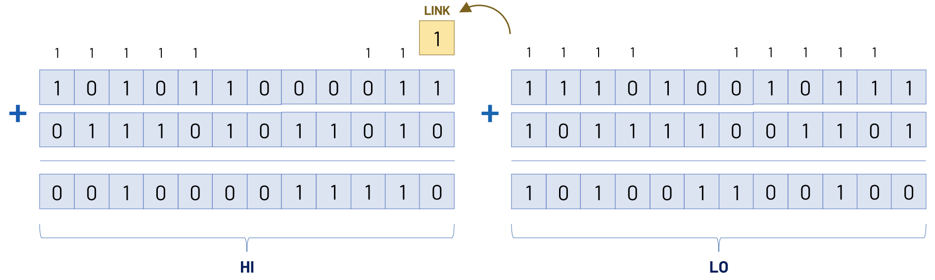
For example, if you want to add two 24-bit numbers, you could store each number in two 12-bit words (HI and LO). You add the low words first; the carry appears in LINK. Then you add the high words and incorporate that carry. This way, our software can construct a 24-bit adder out of a 12-bit adder.
How was the PDP-8 Programmed?
The earliest way of programming one was much more primitive, and there are really three stages of programming style for the PDP-8 worth separating:
- Front-panel programming
- Paper-tape machine code
- Assembly language and assemblers
1. Front panel
At first, you could literally enter the program in binary. The original PDP-8 had a front panel with switches. You could set the switches to represent a 12-bit word, press the appropriate controls, and deposit that word into memory.
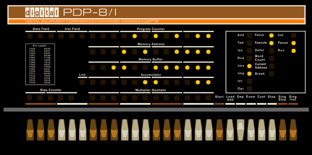
If you wanted memory location 0200 to contain an instruction, you'd manually enter its binary representation:
101 001 000 001You'd set the switches, load the address, deposit the word, increment the address, and repeat. Essentially machine-code programming by hand.
It was wonderfully educational but not optimal for writing anything substantial.
2. Paper tape
As technology and processes evolved, programs could also be stored on punched paper tape. You could punch a sequence of 12-bit words onto tape and load it into the machine. This made it possible to save programs and bootstrap more sophisticated software.
The PDP-8's early software ecosystem was heavily based around paper tape. Later systems could use other storage devices, including DECtape and disk systems.
3. Assemblers
Things became much nicer with assemblers. Instead of writing raw binary, you could write something like:
     CLA
     TAD VALUE
     DCA RESULT
     JMP LOOP

VALUE,  5
RESULT, 0
|
And have an assembler translate the mnemonics into the 12-bit machine instructions.
DEC provided assemblers for the PDP-8 family, and one of the important early ones was PAL (PDP-8 Assembly Language) system.
Toward the end of the PDP-8 era, operating systems such as OS/8 and COS-310 allowed a traditional line-mode editor and command-line compiler development system using languages such as PAL-III assembly language, FORTRAN, BASIC, and DIBOL.
Fibonacci Sequence in PDP-8 Assembly
It's a rite of passage for any programmer learning a new assembly dialect to write a small program that computes and stores the following sequence in memory.
1, 1, 2, 3, 5, 8, 13, 21, ...Here is a straightforward version:
     *0200

     CLA
     TAD ONE
     DCA A

     TAD ONE
     DCA B

LOOP, CLA
     TAD A
     TAD B
     DCA NEXT

     TAD B
     DCA A

     TAD NEXT
     DCA B

     JMP LOOP

A,    0
B,    0
NEXT, 0
ONE,  1
|
The version above is intentionally simple. An improved PDP-8 program could:
- Print the Fibonacci numbers through the console teletype
- use
ISZ(Increment and Skip if Zero) to implement a loop counter - Jump to a subroutine with
JMSfor output - Handle multi-word integers so we can calculate numbers larger than 2047
- Use indirect addressing (I bit flag)
- Store the entire sequence in a memory buffer
Doing More than One Thing
You'll see some instructions in the PDP-8 that combine operations in one single instruction.
DCA Combines Store & Clear
Another PDP-8 instruction worth taking a closer look is DCA (Deposit & Clear Accumulator).
As the name suggests, it doesn't simply store AC into memory. It stores AC and then clears the accumulator.
Why would you design an instruction this way? Well, because it saves hardware and control steps!
After you've finished using the accumulator's value and deposited it into memory, there's often no reason to keep the old value around. So, the PDP-8 combines the two operations.
ISZ Combines Increment & Branch
Another example of this approach of doing more than one thing per instruction is the ISZ instruction. In simple terms, the opcode is telling the CPU to increment memory location X, and skip the next instruction if the result is zero.
Why combine incrementing with branching? Because it gives you a very cheap loop primitive.
Imagine a counter that starts at some value and eventually wraps through zero.
ISZ COUNT JMP LOOPIf COUNT doesn't become zero, execution continues with the JMP. But if COUNT becomes zero, the processor skips the jump.
That's a loop! Two instructions.
Subroutines Don't Need a Stack
Modern CPUs generally make function calls feel like a fundamental operation. In most cases, you call a function and:
- The CPU saves a return address
- A stack pointer moves
- The function returns
The PDP-8 does not have a conventional hardware stack.
Instead, JMS (Jump to Subroutine) uses memory.
The return address is stored in memory associated with the subroutine entry, and the subroutine can return using an indirect jump through that saved address.
What JMS Actually Does?
JMS stores the return address in ordinary RAM (at the first word of the subroutine) and then jumps to the next word; the subroutine returns with an indirect jump through that stored address.
Imagine we have the following code:
1000:  JMS  2000
1001:  ...       ; instruction after the call
1002:  ...
...
2000:  0         ; reserved word (12 bits) for the return address
2001:  ...       ; subroutine starts here
2002:  ...
Jumping to a Subroutine is effectively doing two things:
- Store the current PC in memory location 2000
- Jump to address 2001
The subroutine can then return by doing an indirect jump through location 2000:
JMP I 2000This means subroutine linkage is fundamentally a memory operation; there's no special call stack hardware hiding underneath it.
OPR: Instructions Made Out of Bits
The OPR opcdode is another extremely interesting parts of the PDP-8 architecture.
Rather than assigning every possible operation its own opcode, the PDP-8 uses individual bits inside an OPR instruction to request operations.
In other words, an instruction can effectively say:
clear AC + complement AC + rotate + ...All within the same 12-bit instruction word. The combination of bits determines which micro-operations occur.
This is very different from the mental model many people have of assembly language. We often tend to think "one opcode, one operation."
The PDP-8 shows us another possibility, where the instruction bits act like a collection of hardware control signals.
In that sense, an OPR instruction is almost a tiny piece of microcode embedded directly in the instruction word.
I/O is Part of the Instruction Set
When we think of the PDP-8, the exact peripherals depended heavily on the model and configuration. A typical system could have things like:
- Teletype terminal: keyboard input and printer output
- Paper-tape reader: loading programs/data from punched tape
- Paper-tape punch: producing punched tape
- Printers
- Card readers
- Displays: point-plotting and storage-tube
- Real-time clocks
- Analog-to-digital converters
- Disk storage
- Magnetic tape
- Various lab equipment connected to the system
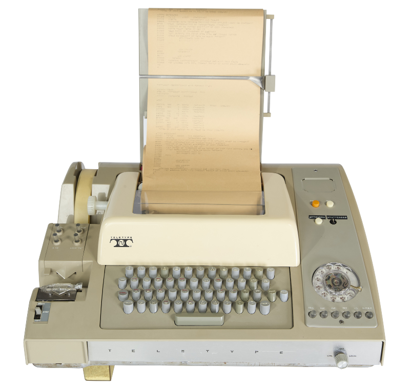
The original PDP-8's console Teletype was commonly an ASR-33, which combined a keyboard, printer, paper-tape reader, and paper-tape punch.
The IOT Instruction
The PDP-8 doesn't have a modern peripheral bus with a huge standardized hierarchy of controllers. Instead, it has the IOT instruction.
The instruction word contains fields identifying an I/O device and an operation.
There are enough bits to select among a substantial number of device codes and operations, and the exact meaning of an IOT is determined by the connected device.
An IOT instruction has this general structure:
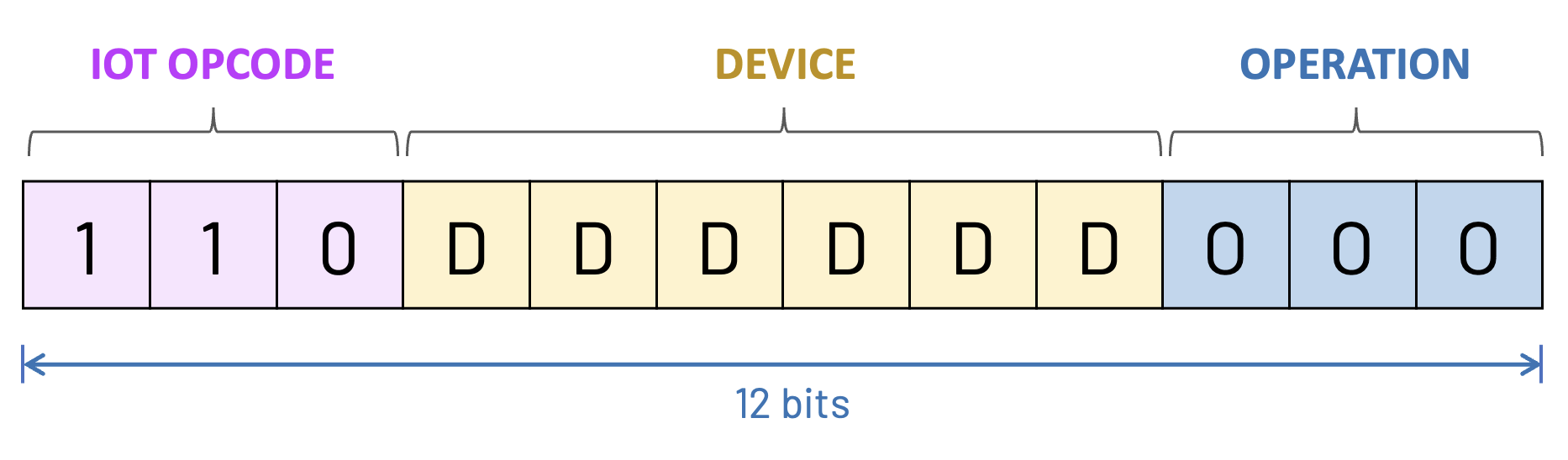
There are 64 possible device codes because the device field is six bits wide.
KSF (Keyboard Skip if Flag), KRB (Keyboard Read Buffer), and TSF (Teleprinter Skip if Flag). Although these look like separate instructions, they are actually all variations of the same IOT instruction. Each mnemonic simply represents a particular combination of device number and operation bits within the 12-bit IOT instruction. The assembler translates the mnemonic into the corresponding bit pattern for you.
The CPU Does Not Know About Peripherals
The CPU doesn't need to know what a printer, paper-tape reader, or oscilloscope actually is. So, you could add a new peripheral without adding a new fundamental CPU instruction.
It essentially says: "Here's an IOT instruction addressed to device 04. I'll put the appropriate signals on the I/O bus. If you've got hardware listening to that device number, you decide what to do."
How Fast was the PDP-8?
Well, that depends on which PDP-8 model we are talking about, since the family evolved considerably. But the original 1965 PDP-8 was extremely slow by modern standards—and surprisingly capable for its time.
The PDP-8 didn't work like a modern CPU where we'd say, for example, "3.5 GHz" and use that as a useful description of its performance. Its timing was closely tied to memory cycles.
The original PDP-8 had a basic memory cycle of about 1.5 μs. A typical memory-reference instruction required multiple memory cycles, so the effective instruction rate was on the order of hundreds of thousands of instructions per second, depending on the instruction and memory configuration.
An addition in the original PDP-8 could be performed in about 3 μs. The PDP-8/S took about 36 μs—roughly. The PDP-8/S's core-memory cycle was about 8 μs.
| Model | Era | Performance |
|---|---|---|
| PDP-8 | 1965 | ~3 μs per TAD |
| PDP-8/S | 1966 | ~36 μs per TAD |
The PDP-8/S is clearly the odd one out in the above comparison. Observe the 36 μs addition value from the PDP-8/S. This illustrates exactly why the cheaper /S exists. Instead of building a 12-bit-wide datapath, DEC processed data serially, one bit at a time. This dramatically reduced the amount of hardware required, but at a price: an addition that took about 3 μs on the original PDP-8 took roughly 36 μs on the PDP-8/S. In other words, the 8/S traded hardware for time.
Later models, like the PDP-8/I and the PDP-8/E had around ~1.5 μs memory cicle.
Core Memory Changes the Way You Think About Time
The original PDP-8 used magnetic core memory, which stores bits using tiny magnetic cores threaded by wires.
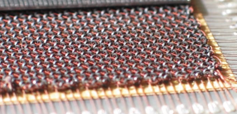
Unlike modern RAM, this isn't a sea of microscopic transistors in a silicon chip. It's a physical grid of magnetic components.
This is why we mentioned the speed of the PDP-8 models in terms of memory cycles. Memory was slow enough that the processor's timing was strongly tied to the computer's memory cycle.
When you design a CPU today, we tend to think of the processor as the fast thing and memory as the slow thing. But in the PDP-8, the CPU itself is relatively simple, and much of the machine's rhythm is dictated by the memory technology.
Therefore, the physical implementation of memory had a direct influence on the timing of the processor.
Conclusion
The PDP-8 is a nice reminder of what's hiding underneath. If you are learning with us how basic computer circuits work, and if you can understand how a few logic gates can become an adder, and how an adder can become part of an ALU, and how an ALU and a handful of registers can become a CPU, then you've already understood a crucial part of what a computer really is. Everything else is another layer of abstraction.
That is exactly what makes machines like the PDP-8 so much fun to study! You can peel those layers back one at a time, until an assembly instruction like TAD A isn't mysterious anymore.
Another historical reason why the PDP-8 became so influential was that it was designed to be open. DEC's documentation and hardware information made the machine unusually accessible for the time. Universities and laboratories could study the machine, modify it, and build interfaces for it. Third-party hardware and specialized systems appeared around the architecture.
This mattered enormously. A computer that you can understand and modify becomes something different from a computer that you merely rent and operate.
- Engineers could use the PDP-8 as a component in a larger system
- Laboratories could connect their own instruments
- Manufacturers could build specialized controllers
- Students could learn how the machine actually worked
The PDP-8 was not just a computer we bought or rented. It was a computer we could build things around!